

CAD DRAWINGS: WHAT THEY ARE, THE TYPES AND THE FILE FORMATS

A CAD drawing is a technical drawing made in software rather than on paper. Sounds like a small difference. It really is not.
Scan a hand drawing and you get a picture of some lines. A CAD drawing is the lines themselves. Every wall is an object that knows its own length, everything sits on a layer, and the drawing is made at full size and only scaled when it hits a sheet. Measure something on it and the number is true.
With a wide range of CAD programs available today, professionals can choose software tailored to their specific needs, from civil engineering to electrical planning. But with so many different programs, how can teams collaborate effectively when each program uses a different file type?
Our architectural drafting studio has compiled a list of the five most popular and universal CAD file formats that ensure seamless collaboration across various platforms.
Five formats do most of the work in architectural drafting. The rest of this article walks through them one by one, then covers the stragglers that show up anyway, and closes with the questions clients send us week after week.
Contents:
- What a CAD drawing actually is
- The types you will be asked for
- 2D or 3D
- The file formats
- How a CAD drawing gets made
- What separates a good set from a bad one
- CAD drawings FAQ
What a CAD Drawing Actually Is
Three things separate it from a nice image of a drawing.
The first is real geometry. Nothing is sketched to look about right, it is drawn full size, and the scale only appears at printing. Our AutoCAD scale factor chart and calculator covers every scale you are likely to plot at. Nobody has to hold a ruler against a legend.
The second is layers. Walls, dimensions, furniture, electrics and annotation each live on their own, so a contractor switches off what does not concern him and prints what does.
The third is data hiding inside the objects. A door is not four lines. It is a door, with a width and a swing and a tag, and it counts itself when somebody builds a schedule. The same reasoning explains why practices moved off the drawing board in the first place, and why architectural CAD drawings turned into the default rather than an option.
That third one is where CAD quietly stops being a drawing tool and turns into a database, which is the whole idea behind BIM.
The Types You Will Be Asked For
Here is the thing: nobody actually orders a CAD drawing. They order a set, and what goes in it depends on what happens next. The full breakdown is in our guide to CAD drawing types, and the same split by discipline is in the 5 basic types of drafting.
Floor plans come first, a horizontal cut about a metre up looking down, and everything else hangs off them. Elevations and sections handle the vertical half of the story, which is where ceiling drops and the thing hiding behind a finish show up. Details go closer still, usually 1:5 or 1:10, to settle exactly how two materials meet.
Then there are schedules, which count doors and windows and finishes so somebody can price them. Shop drawings are a different animal altogether, made by whoever fabricates the item rather than by the designer. And as-built drawings record what was really constructed, which is almost never what was drawn.
On interiors the list runs longer again, and we set it out in the types of interior design drawings.
2D or 3D
Both on most projects, and for different reasons.
2D is what gets built from. Faster to produce, prints without argument, and a foreman can read it on site in the rain. 3D is what gets approved: a model catches clashes a flat plan hides, and a client understands it without anyone walking them through it.
In practice the model produces the sheets anyway, so the real question is not either-or but which end you start from. We put the two side by side in 2D against 3D CAD services.
The File Formats, and Which One to Ask For
A drawing is only useful if the other side can open it. These are the five that cover almost everything you will be sent.
DWG
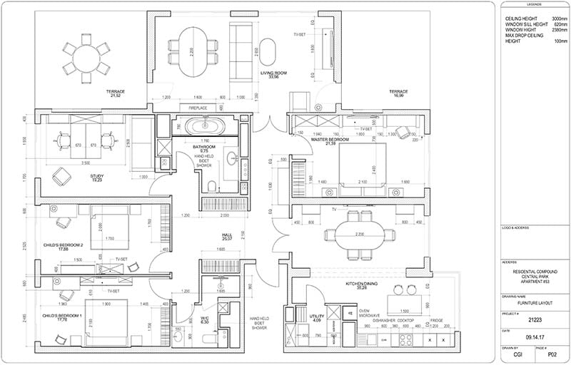
A DWG file is a type of CAD file used in AutoCAD that stores metadata and 2D or 3D vector image drawings. As one of the most widely used CAD file formats, DWG is a staple in the architecture, construction, and design industries. Autodesk froze the format back in 2018 and has not touched it since, so a drawing saved today opens fine in a seven year old AutoCAD. Going the other way is the problem. If a shop runs something ancient, save them a copy down a few versions and spare everyone the phone call.
The greatest advantage of DWG CAD files is their compatibility with numerous CAD and 3D drawing programs, making it easy to transfer drawings between platforms. DWG CAD files are often regarded as the industry standard for technical drawings and blueprints.
DXF
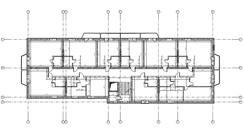
DXF, or Drawing Exchange Format, is a type of CAD file also developed by Autodesk to make sharing CAD files between different software programs easier. DXF format supports both 2D and 3D models, making them versatile for use in product design, architecture, and engineering.
A key benefit of DXF is its ability to facilitate collaboration between professionals using different CAD programs. For instance, an architect and a draftsperson can easily exchange their designs using a single DXF CAD file. Additionally, DXF CAD files can be opened in most vector graphic software, without installing special architectural drafting programs.
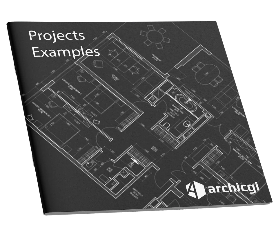
Want to know more about CAD services our studio provides? Check out this archive with projects examples and learn more.
DGN
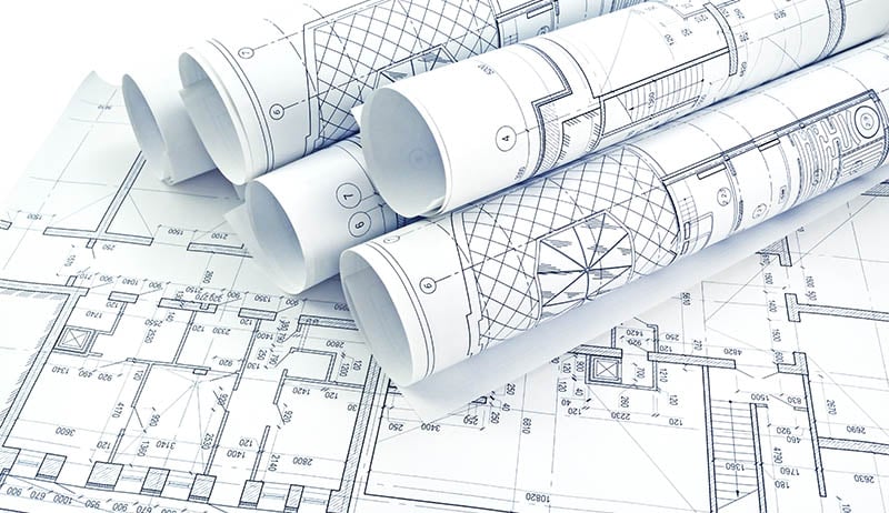
DGN is a CAD file format primarily associated with Bentley Systems’ MicroStation software, though it’s compatible with other CAD applications as well. DGN CAD files are commonly used to store 2D and 3D design data, including drawings, models, and geometric representations. These files are often utilized in large infrastructure projects like roads, bridges, and power plants.
Much like Autodesk’s DWG format, DGN is widely used in civil and infrastructure engineering projects. MicroStation users, along with professionals using other design tools, rely on DGN CAD files for multi-disciplinary collaboration.
RFA
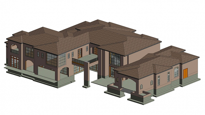
RFA is the family file format of Autodesk Revit. Revit projects rely on files structured around “families,” which are organized components like doors, windows, furniture, and structural elements. RFA CAD files allow these elements to be reused consistently throughout a project.
There are two types of Revit families: system families, which are integrated into the Revit model, and hosted families, which can be stored externally and reused across different projects. RFA CAD files contain not only the geometry of objects but also BIM data, including dimensions and materials, ensuring that projects maintain accuracy and consistency throughout the modeling process.
PLN
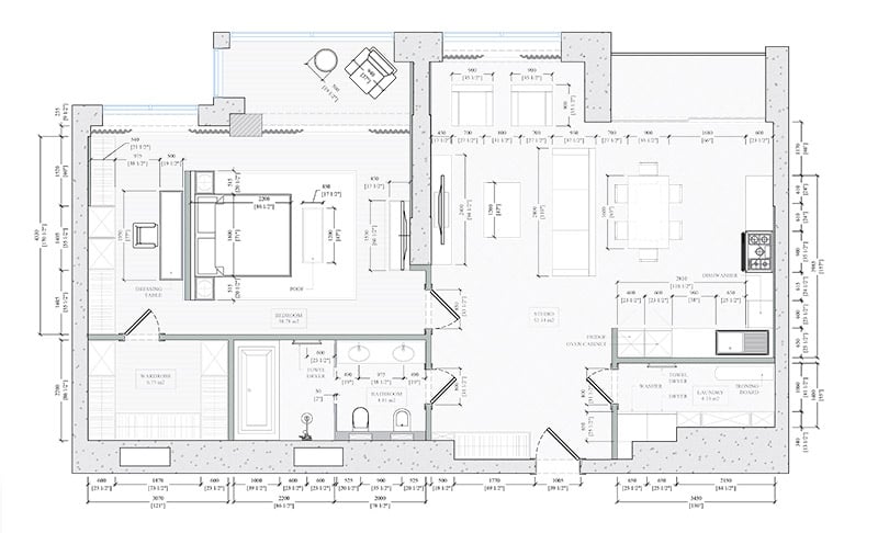
PLN files are a type of CAD file used by Graphisoft ArchiCAD, a BIM software for architectural design. PLN CAD files store all model data and views generated by ArchiCAD, much like RVT or DWG in Revit and AutoCAD. PLN holds the whole project, while library objects such as doors and furniture sit apart in GSM files. On a big residential job that split is what keeps the project file from bloating. Though primarily used in ArchiCAD, PLN CAD files can be exported to other formats, ensuring compatibility with a wide range of design software.
Other formats worth knowing
Five formats cover the textbook cases. Real projects are messier, and a few more names keep landing in the inbox.
IFC exists because nobody agrees on software. The architect models in Revit, the structural engineer swears by Tekla, the facade consultant runs ArchiCAD. Everyone exports IFC, the files meet in one coordination model, and the clash report shows whose duct runs through whose beam.
RVT is the Revit project itself. The whole building sits in there with views, sheets and schedules, while RFA families are just the parts bin. Clients on Revit get the RVT. Everyone else gets IFC plus a PDF set.
PDF is not CAD at all, yet present in every project folder on earth. It prints, it emails, a permit office clerk can open it. What it cannot do is be edited as geometry. Half of our conversion work starts with somebody who only has the PDF left.
SKP comes from SketchUp, usually from a designer who blocked out an idea in one afternoon. The geometry imports fine. The cleanup takes longer than the import.
STEP and STL belong to manufacturing. STEP moves exact solids between mechanical CAD systems, STL feeds mesh geometry to 3D printers. Order custom hardware for a furniture line and one of the two will land in your inbox.
The majority of these CAD files are universal and can be opened in most major architectural CAD programs. They also export easily to other software, enabling smooth communication and collaboration between teams across different disciplines. In many cases, these CAD file formats can be opened without dedicated CAD programs, making them accessible in vector graphic software as well.
How a CAD Drawing Gets Made
Measurements come first, whether that is a survey, an old blueprint, a point cloud off a laser scan, or a sketch with dimensions scribbled on it. Every error at this stage travels all the way down the set.
Setup is next. Template, title block, layer standard, units. Ten minutes here saves a redraw later, and skipping it is the single most common way a project loses a week.
Then the drawing itself, structure before finishes, followed by a coordination pass where the plan and the sections and the schedules get checked against each other. After that somebody who has not been staring at the file for a fortnight reviews it, and only then does it go out. The stage-by-stage version is in the CAD drafting process.
Two rounds of corrections after delivery are normal and should already sit in the price.
What Separates a Good Set From a Bad One
Here is a test you can run without being a drafter. Before running it, it helps to know what a full set is supposed to contain, because a sheet cannot be judged against a standard nobody named.
Is there a scale on every sheet, and are walls drawn at their real thickness? Can you tell which way each door opens? Are rooms named and dimensioned, and do the dimensions on the plan agree with the ones on the section? Is there a title block with a revision number, so anybody can tell whether they are holding the current version?
Miss any of those and what you have is a picture of a drawing. Somebody on site will guess, and that guess costs more than the sheet ever did. Most of that risk is settled before drawing starts, in the handful of things worth knowing before you order and in the technical drawing conventions the set is drawn to. If you would rather not run that check yourself, our CAD drafting services start at $20 per hour, with a free hour estimate before anything begins.
Wonder how much high-quality drafting services cost? Check out the examples of our real projects with pricing.
Need professional, precise CAD drawings for your project? Our architectural drafting services deliver top-quality blueprints in any format you need!
For more details, read about what affects the cost of CAD drawings and the advantages of drafting in AutoCAD. Need this done for you? See our CAD conversion services.
CAD Drawings FAQ
What is a CAD drawing?
A technical drawing produced in software rather than by hand. The lines are real objects with real lengths, everything sits on layers, and the whole thing is drawn full size and scaled only at printing. That is why you can measure something on it and trust the number, which was never quite true of a scanned paper drawing.
What types of CAD drawings are there?
A project needs a set rather than a drawing. Floor plans, elevations, sections, details and schedules make up most of it. Shop drawings sit apart, produced by the fabricator instead of the designer, and as-built drawings record what was actually built once the dust settles.
Who makes CAD drawings?
Drafters, working from an architect’s or designer’s intent. It is a separate craft from design: the designer decides where the wall goes, the drafter makes the sheet that lets somebody build it there. On smaller jobs one person does both, which is usually where the errors creep in.
How much does a CAD drawing cost?
We bill $20 an hour for drafting and $25 for Revit and BIM. A single dimensioned plan lands in a few hours. A full set runs into the tens of hours, and the honest answer depends far more on what you send us than on the number of sheets.
What is the difference between DWG and DXF?
DWG is what AutoCAD actually works in: binary, compact, everything included. DXF takes the same drawing and spells it out in a text form other programs can parse. The price is file size and, sometimes, dumber objects on the receiving end. Our habit is to draft in DWG and export DXF only when the other side’s software leaves no choice.
What CAD file format do architects use most?
For 2D construction sets, DWG, and it is not close. BIM offices live in RVT or PLN and trade IFC between consultants. PDF goes to everyone who does not draft: clients, permit offices, banks.
Can a PDF be converted back into a DWG file?
Yes, with a catch. If the PDF was exported from CAD, the vectors survive and the work is mostly rebuilding layers, dimensions and line weights. If it is a scan of a thirty year old blueprint, someone redraws it by hand over the raster. We do both, and hand redrawing often beats cleaning up what an automatic converter spits out.
Which file format should I request when ordering CAD drawings?
The editable source plus a print set. That means DWG for drafting work or RVT for BIM, and PDFs of every sheet on top. Tell the drafting company what software your side runs before work starts. That costs one sentence in a brief and saves a week of file juggling.
What format is used for BIM collaboration?
IFC. Revit, ArchiCAD, Tekla and the rest all export it, so each office keeps its native files and shares a neutral copy for coordination. You cannot edit an IFC the way you edit the source model, which annoys people exactly once, and then they realize that is the point.

Nathalie Paul
Blog Writer
Nathalie is a senior draftswoman at ArchiCGI. She loves the fine art of creating quality drawings. After work, Nathalie is passionate about Ishvara yoga, traveling, and strong bitter coffee.


Leave a Reply
Want to join the discussion?Feel free to contribute!