
Architectural Symbols on Construction Drawings, Explained by Drafters
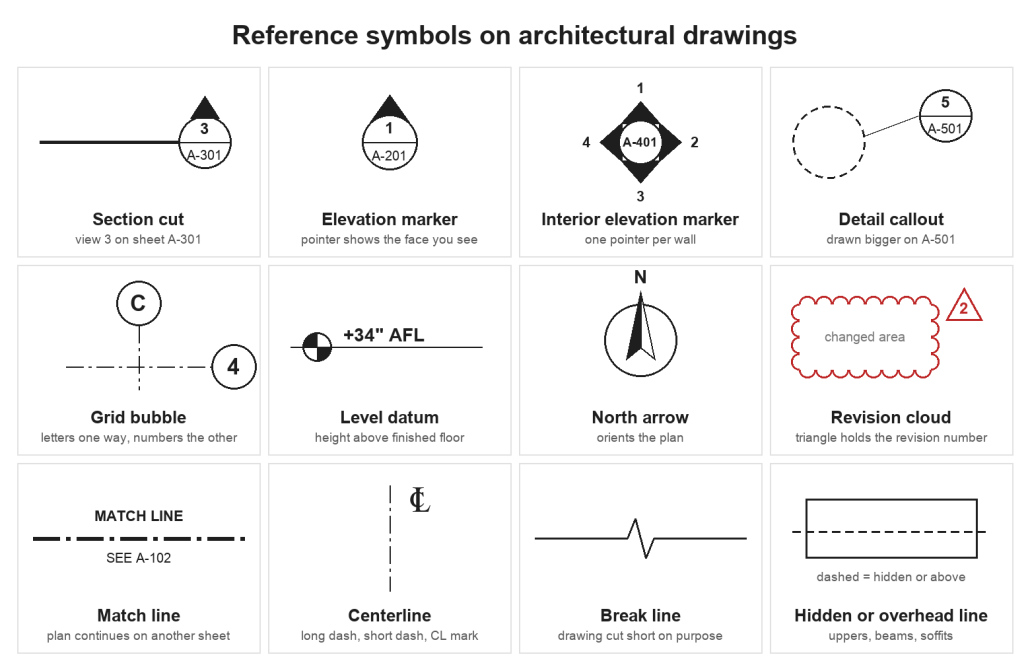
The twelve reference marks you will meet on almost any set. Shapes vary a little by office.
Architectural symbols are the shorthand of a drawing set. A circle with two numbers, a hexagon on a door, a little flag over a wall. Each one stands for something that would take a paragraph to write out, and most of them point you to another sheet.
We draw these all day, on our own sets and on other people’s, so this guide sorts them the way you meet them on real sheets: the marks that send you somewhere else, the tags that name things, the floor plan symbols, the lines and hatches, and the abbreviations that fill whatever space is left.
Contents:
- Reference symbols: the ones that send you to another sheet
- Tags: doors, windows, rooms and finishes
- Floor plan symbols
- Lines and hatch patterns
- Electrical and plumbing symbols on architectural sheets
- Construction abbreviations
- The legend decides
- Architectural symbols FAQ
Reference symbols: the ones that send you to another sheet
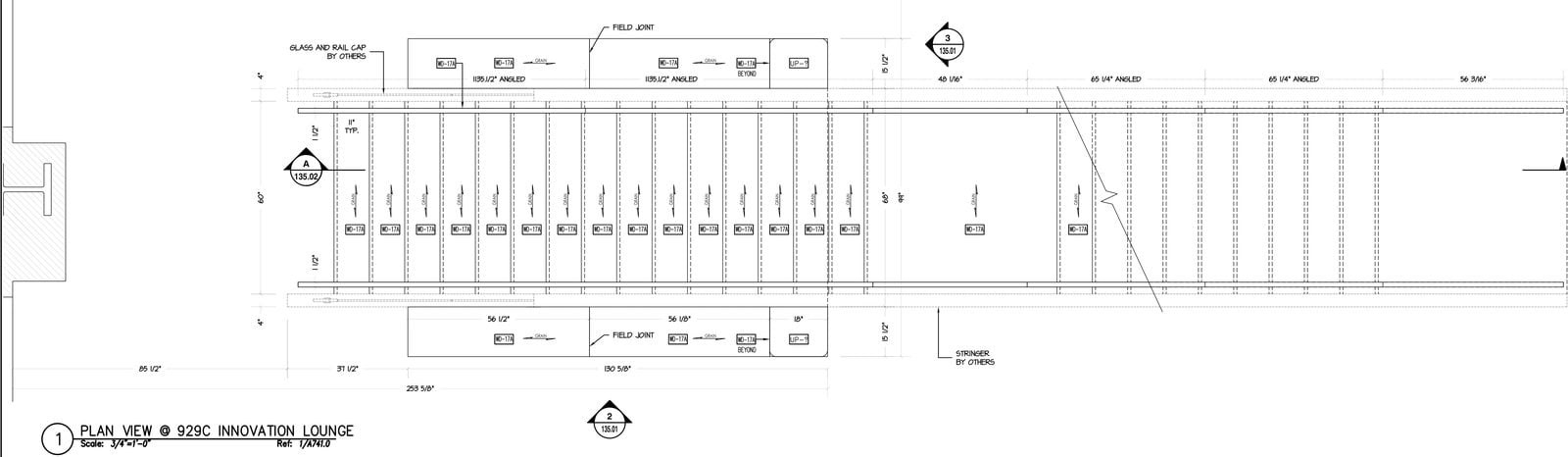
A stair plan from one of our shop drawing sets. Three section marks, a break line where the run is cut short, a finish tag on every tread.
If you learn one group, learn this one. Almost every reference symbol is a circle split in two. The top half is the view number, the bottom half is the sheet it lives on. So 3 over A-301 reads “view 3 on sheet A-301”. The pointy part shows which way you’re looking.
A section cut is a line across the plan with one of those bubbles at the end, sometimes at both ends. The arrow or the filled triangle tells you which side of the cut you’ll see in the section. An exterior elevation marker is the same bubble with a single pointer aimed at a face of the building.
Interior elevations get a marker with up to four pointers, one per wall, usually set in the middle of a room. Each pointer has its own number. You’ll see a version of this on the elevation key plan in our architectural drawings guide, where one marker per bedroom leads to four elevations on the next sheet.
A detail callout is a circle or a cloud drawn around a small area, with a leader to a bubble that names the detail. Wherever the drawing gets too small to explain a joint, a callout says “this part is drawn bigger over there”. Enlarged plans of kitchens and bathrooms are called out the same way, with a box instead of a circle.
Grid bubbles sit at the ends of the structural grid lines, letters one way and numbers the other. They’re how everyone on site agrees on a location. “Near C-4” means the same spot on every sheet in the set, the structural ones included.
A handful more don’t send you anywhere, and people still trip over them. The quartered circle with a number beside it is a level mark: +34″ AFL is 34 inches above the finished floor, nothing more mysterious than that. The north arrow does what it says. A match line means you’ve run off the edge and the plan carries on elsewhere. And the wavy cloud with a little triangle? Somebody changed something. The number in the triangle is the revision, and the title block tells you when and why.
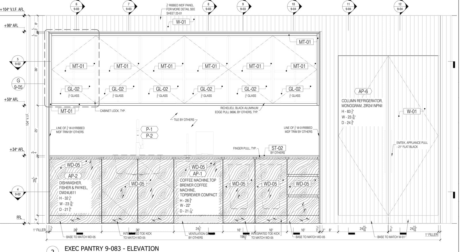
Section marks across the top and down the left, level marks at each height, a tag on every door and appliance.
Now on a real sheet. The pantry elevation above has section marks down the left side pointing to sheet 9-02, a detail bubble pointing to 9-05, level marks at every key height and tags on every cabinet and appliance. Nothing on it is decoration.
Tags: doors, windows, rooms and finishes
Tags name things so the plan doesn’t have to. A tag is a short code in a shape, and the code is looked up somewhere else, usually in a schedule or a legend.
Door tags get searched more than any other, probably because everyone has had a door arrive the wrong size. You take the number off the plan, find its row in the door schedule, and there’s the size, the type, the frame, the rating and the hardware. Windows do the same thing, sometimes with a letter, sometimes in a diamond. One office uses hexagons, the next uses circles. We stopped caring about the shape years ago. We care whether the tag has a row to land on.
A room tag is just the room’s name and number, plus area and ceiling height if the office likes them. The small shape sitting on a wall, often a diamond, is a wall type, and somewhere in the general sheets there’s a drawing of what that wall is made of. Keynotes are numbers in a square that refer to a list of notes on the side of the sheet, which keeps long text off the drawing.
Interior and millwork sheets are covered in finish tags, WD-05, MT-01, ST-02, usually in a box with rounded corners. WD is wood, MT metal, ST stone, GL glass, and the finish schedule says exactly which wood and which metal. Appliance tags, AP-3 and so on, do the same for equipment, with model numbers and sizes in a table. When a tag has no line in its schedule, it’s a question for the architect, and it’s one of the most common ones we send.
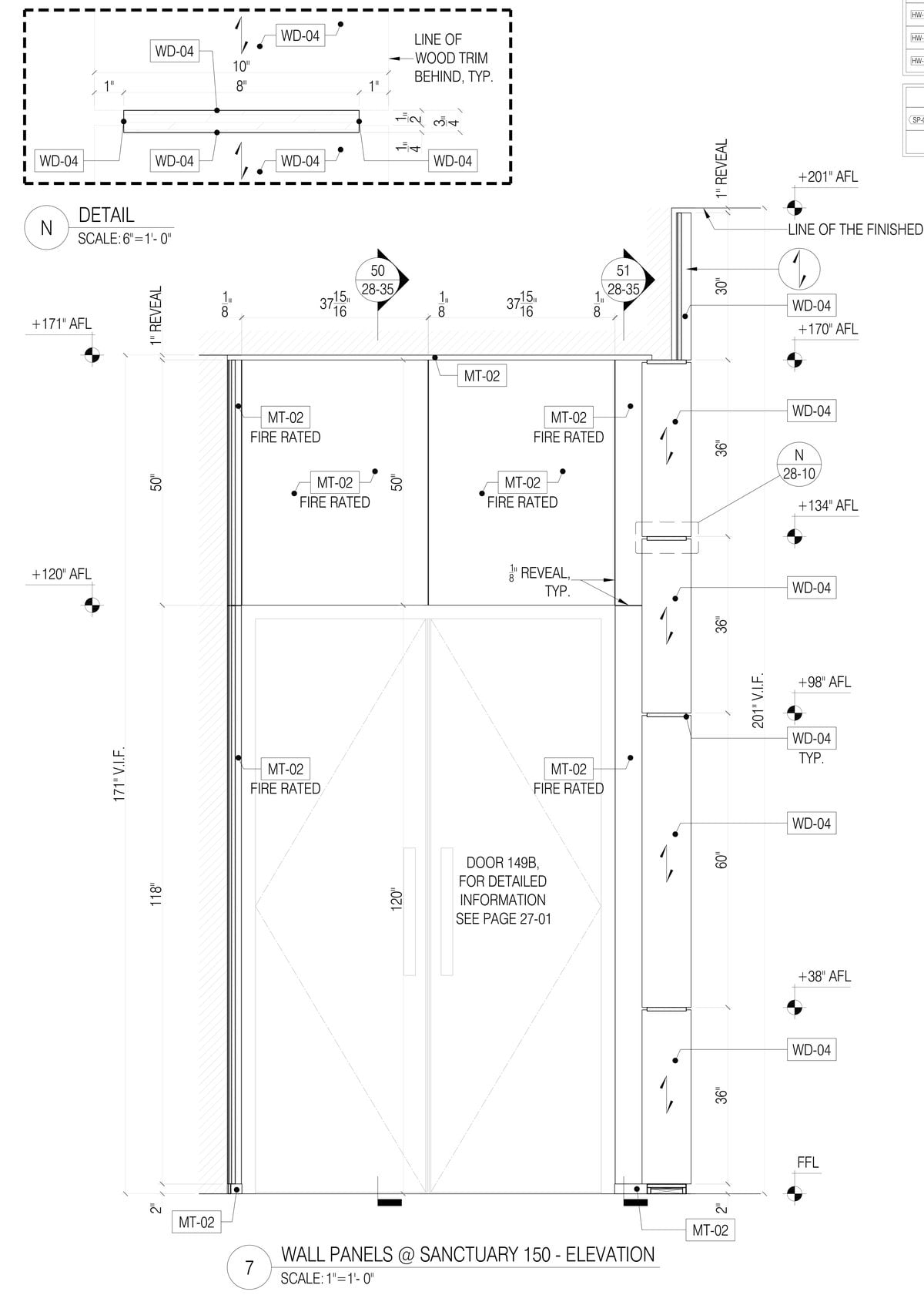
Finish tags on every panel, a callout to detail N, and a door note that sends you to page 27-01.
Floor plan symbols
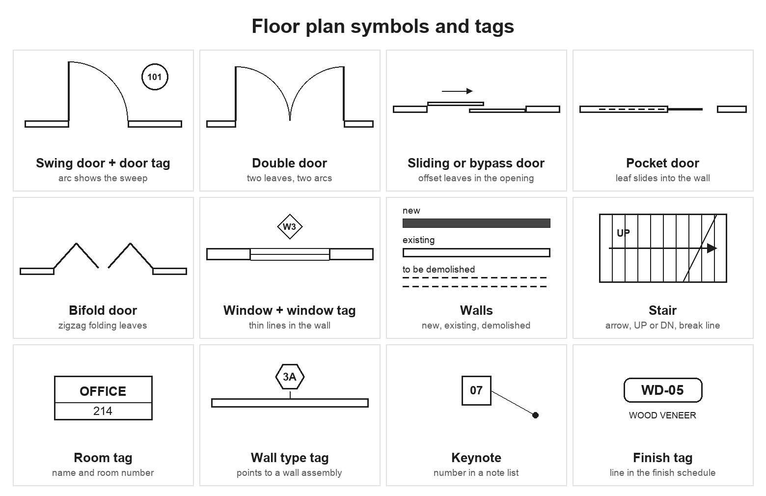
Common floor plan symbols and tags. Door and window tag shapes are the part that changes most between offices.
Floor plan symbols are closer to little pictures. Walls are drawn as two lines. New walls are often filled or hatched, existing walls are left as outlines, and walls to be demolished are dashed. A renovation set usually has a separate demolition plan, so you’re not reading all three at once.
A swing door is a line for the leaf and a quarter circle for the path it sweeps, so you can see what it hits. Double doors get two arcs. Sliding and bypass doors are drawn as offset lines in the opening, pocket doors as a leaf disappearing into the wall, and bifolds as a small zigzag. Windows are thin parallel lines in the wall, usually three, with the sill sometimes shown.
Stairs are drawn as treads with an arrow and the word UP or DN, and a diagonal break line where the floor plan cuts through them. That break line is the same one used anywhere a drawing is cut short on purpose. Columns show as small filled squares or circles sitting on the grid.
Lines and hatch patterns
Half of what a drawing tells you is in the line itself. See it, and it’s solid. Can’t see it because it’s above you or behind something, like the upper cabinets on a kitchen plan, and it’s dashed. Long dash, short dash is a centerline, and the CL mark, a C with an L laid over it, flags the center of an opening or a sink when that center matters. Cut things get heavy lines, things in the distance get thin ones. Squint at a good plan and you can still read it from the line weights alone.
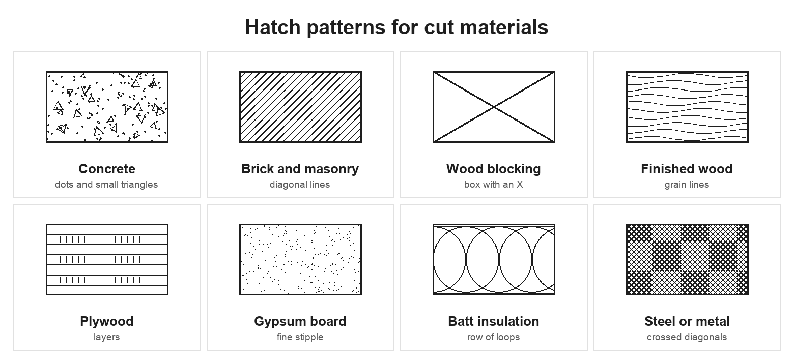
Eight hatches you see in sections. The box with an X turns up on nearly every millwork section we draw.
Hatches fill whatever has been cut, so you can tell the materials apart in a section. Concrete is dots and small triangles. Brick and masonry are diagonal lines. Rough wood blocking is a rectangle with an X through it, and you’ll see that box on nearly every millwork section we draw, marked “in-wall blocking by others”. Finished wood shows grain, plywood shows its layers, batt insulation is a row of loops. Offices tweak these, so the legend still has the last word, but most of them are common enough that you’ll recognise them on any set.
If you want more on how cut lines and hatches work together, our article on section drawing goes into it.
Electrical and plumbing symbols on architectural sheets
The apartment set in our architectural drawings guide has separate sheets for switches, outlets, lighting and plumbing, and most residential interior sets do. You’ll find the usual suspects: a circle with two ticks for a duplex outlet, an S, or a $ on older sets, for a switch, circles and squares for lights, and plumbing fixtures drawn as outlines of the real thing. Those sheets say where. How big the circuit is, or the pipe, is on the engineers’ drawings, with their own legend.
Construction abbreviations
Abbreviations fill every corner of a sheet, and a few of them carry a lot of weight. These are the ones we see on almost every job:
| Abbreviation | Means | What it tells you |
|---|---|---|
| AFF / AFL | Above finished floor | Heights of counters, outlets, shelves |
| VIF | Verify in field | Measure on site before building |
| TYP | Typical | Same everywhere this condition repeats |
| U.N.O. | Unless noted otherwise | The default, until a note says different |
| EQ | Equal | Spaces split evenly |
| CLR | Clear | Open dimension between finished faces |
| NIC | Not in contract | Shown for reference, someone else supplies it |
| BY OTHERS | By others | Another trade supplies or installs it |
| CL | Centerline | Dimension taken to the center of something |
| FFL / FFE | Finished floor level / elevation | The zero line heights are measured from |
| GWB / GYP | Gypsum wall board | Drywall |
| SIM | Similar | Like the referenced detail, with small differences |
| N.T.S. | Not to scale | Do not measure this view |
| O.C. | On center | Spacing measured center to center |
| DN / UP | Down / up | Direction of stairs and ramps |
| EXIST / (E) | Existing | Already there, stays unless noted |
| RCP | Reflected ceiling plan | The ceiling sheet |
| HM / SC | Hollow metal / solid core | Common door types in schedules |
Abbreviations we see on almost every set. Check the list on sheet one for the rest.
Most sets have an abbreviations list on the first sheet. If an abbreviation isn’t on it, don’t guess, ask.
The legend decides
Yes, there’s a standard. In the US it’s the National CAD Standard, and most offices begin there. Then they change it, a little or a lot, and print their own legend. Which is fine, as long as you read that legend before anything else. Think of this guide as knowing roughly what you’re looking for.
When a set lands on our desk from another office, we check one thing before anything else: do the symbols on the sheets match the legend on sheet one? Mostly, yes. Where they don’t is exactly where the RFIs will come from later. If you need a set drawn with consistent symbols in your own title block and standards, that’s what our interior drawing services and millwork shop drawing services pages are about. For the bigger picture of what a full set contains, see our guide to construction documents.
Architectural symbols FAQ
What do the symbols on a floor plan mean?
If it looks like a door, a stair or a toilet seen from the ceiling, that’s what it is. Numbers sitting in little shapes are lookups, so go find the schedule or the sheet they name. Whatever’s still a mystery after that, the legend on page one should clear up. Most plans make sense once you’ve split the marks into those two groups.
What does a circle with two numbers mean on a drawing?
Read it upside down, sheet first. Say the bubble says 5 over A-501. Down there at the bottom, A-501, that’s the sheet you need. Up top, 5, that’s the drawing on it. Then look at what’s stuck to the bubble. A long cut line across the plan, and you’ll land on a section. A leader into a cloud, a detail. Just a little arrow aimed at a wall, an elevation.
What is a door tag?
Every door on the plan has one, a short number in a circle or a hexagon or whatever shape that office prefers. Take the number to the door schedule and you’ve got everything: size, type, frame, rating, hardware. When we get a plan where a tag has no row in the schedule, that’s usually the first RFI we write.
What does VIF mean on drawings?
Verify in field. It’s the drafter being honest: this number came from the best information we had, and somebody needs to put a tape on it before anything is cut. On millwork it’s nearly always a wall length or a ceiling height.
What does TYP mean on a drawing?
Typical, as in ‘this happens everywhere it looks like this’. Drafters use it so they don’t have to repeat one note forty times. It usually travels with U.N.O., unless noted otherwise, and between the two of them they cover most of the exceptions on a sheet.
What is a revision cloud?
That bumpy outline someone drew around part of the sheet? It means this bit changed since you last saw it. The small triangle beside it carries the revision number, and if you look in the title block you’ll find that number again with a date. A reissued sheet with no clouds at all is always worth a phone call.
Are architectural symbols standardized?
More than people fear, less than they’d like. Most US offices begin from the National CAD Standard, so a section mark from Denver looks a lot like one from Boston. Then each office bends it, and door tags alone come in circles, squares and hexagons. Read the legend first and you won’t get caught.
Wonder how much high-quality drafting services cost? Check out the examples of our real projects with pricing.

Nathalie Paul
Blog Writer
Nathalie is a senior draftswoman at ArchiCGI. She loves the fine art of creating quality drawings. After work, Nathalie is passionate about Ishvara yoga, traveling, and strong bitter coffee.
